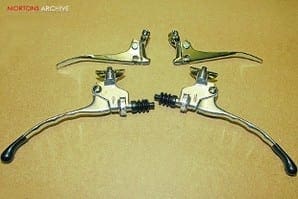
Clip fixing and brake levers
Some makers of early pioneer machines, such as Minerva, Sun and Hobart, often employed cycle-type brake levers rather than inverted levers as detailed last month to serve front brake and valve lifter or decompressor valve as appropriate. Others, exampled by Rudge, Triumph and Sunbeam, usually fitted inverted levers for these roles.
When makers started fitting control cable operated clutches, an obvious solution was to use the left hand inverted lever to operate the clutch and fit another lever inboard of this to operate the valve lifter or decompressor valve. Unfortunately, while standard clip fitting brake/clutch levers give an inner cable straight pull of circa 20mm (¾in) most inverted levers offer an inner cable straight pull of circa 12mm (½in).
Enjoy more Classic Bike Guide Magazine reading every month.
Click here to subscribe & save.
As we know, we often need near the full pull of a clutch lever to free a multi-plate clutch and inverted levers simply don’t offer sufficient cable movement to free some clutches. The OEC Blackburne in our workshop employs a small ‘made-up’ lever for the valve lift and the left inverted lever works the clutch. Fine, but precise adjustment is required and clutch plates must free in an absolute true manner, otherwise it drags.
 Makers encountered similar problems – while some stuck to inverted lever clutch operation, others, including Norton, began to favour a clip fitting clutch lever, mounted on the left side of the handlebar, but inboard of the inverted lever, which was retained for valve lifter operation. A popular brand was the Bowden clutch lever which was not only well made from robust castings but offered a more-than-generous inner cable straight pull measurement, enough to free all but the most rottenly set-up clutches.
Although inverted levers still found favour – even after WWII for some autocycles – velomotors and mopeds they were dropped by many makers by the early 1930s in favour of clip fitting clutch and brake levers. Typically, the clamp upon which the lever pivoted was a casting, for example in aluminium bronze as Amal employed for many of their period clip fitting brake and clutch levers. Again typically the lever was a steel pressing.
But there was no standard form in either design or structure. Machines ranging from post WWII James lightweights to BSA Gold Stars used lever pivots welded to the handlebars/clip-ons and pressed steel levers. Some brands’ levers were made of aluminium, including those found on some competition models. The famous Italian maker Tomaselli made its range of Matador alloy levers which builders of race replicas and cafe racers favour, while Amal manufacture alloy ball ended brake and clutch levers with clamp rather than clip fixing. It’s a really neat concept, though they need sliding onto the bars before the grips are fitted.
 During competition work, riders were injured when standard brake and clutch lever ends pierced them. Although most injuries weren’t serious, this had become a sufficiently common off-road occurrence among speedway riders to encourage some to fabricate blunt ends for their levers. During a recent telephone conversation former Dot works rider Eric Adcock he recalled his father fabricating a ‘ball-end’ lever arrangement when helping prepare Eric’s trial machines.
Matters came to a head with the death of scrambler Mike Weedon in 1954, whose leg was pierced by a control lever. Initially Mike didn’t appear too badly injured but he bled to death before reaching medical help. The incident led to the compulsory fitment of ball end levers for competition work. Some favour them for road use too. The brake and clutch lever concept remains for fluid operated systems.
Further control levers
Early pioneers often had a short row of chessman type levers mounted on or close to their frame’s top tube with rod operation to control carburettor and ignition advance/retard. Although odd makers transferred this rod control to the handlebars, the design involved endless knuckle joints to enable operation while the handlebars were moved for steering. Cable control from handlebar levers was the option of many.
Initially carburettor control was often by two levers or a twin lever set-up, as the majority of pioneer instruments weren’t automatic, requiring the rider to regulate mix of air and fuel. Unusually, a few makers employed levers which pushed away from the rider to increase fuel and air supply whereas to pull lever to rider to increase supply seems more natural. Happily most manufacturers later conformed to the later option.
 Once automatic carburettors gained favour and more makers opted for twistgrip control the twin lever disappeared and was replaced by a single lever, if required, to operate the carburettor’s choke. Some makers moved the location of this to an underseat frame tube, or similar, in an effort to de-clutter the handlebars, which is particularly helpful for those building cafe racers with clip-ons, as there is little handlebar length on which to fit all the controls and switchgear. Traditionally makers’ fitted choke control on the right hand bar and magneto control to the left, but this isn’t a hard and fast rule.
Into the late veteran period and even beyond many makers continued with rod advance/retard control to the ignition system from a tank side lever mounted on a machined boss soldered to the fuel tank’s side. The next logical step was a move to handlebar control, often employing a mirror image mate to the choke lever. Many refer to this lever as the magneto or ‘mag’ lever, since it often controlled these, but an identical lever also serves for coil ignition systems with mechanical contact points control mounted on a moveable base within its housing. Some machines, such as some post WWII Velocette singles and later BSA A10s for example, used automatic advance control and didn’t need a manual mag lever.
All such levers which pivot about their clamp rely on friction to prevent them moving from the position chosen by the rider. With some brands, the degree of friction is fixed by the maker and offers no allowance for rider preference or wear; however, often a thin shim will restore friction to prevent the carburettor slide return spring from pulling the lever shut. Other brands of lever may have an adjustment facility.
 Although other than for economy lightweight twistgrip control replaced lever control for many makers by the 1930s, and before, especially for sporting riders, not all were delighted with the change. Irish road racer Stanley Woods stipulated for years a lever instead of a twistgrip for his factory racing models – and which works mechanic was going to argue with a man who won 10 IoM TTs in his long career? Mr Woods’ logic was simple and sound; during the 1920s, the IoM course was so rough in places he liked to set the lever for full power and then the might of both hands were reserved for hanging on and steering…
The final lever, which retained its place on the handlebars well into the 1960s on big singles, was the valve lift lever. Most two-stroke makers had dropped the concept of a decompressor earlier. If the left hand inverted lever was given over to clutch operation or when inverted levers were replaced by clip fitting levers makers opted for smaller, often trigger like levers to work valve lifts and decompressors. You’ll spot Gold Star owners, for example, fingering these as they ease their high compression singles over TDC and into position for starting.
 Twistgrips
Mention the word twistgrip and we all think in terms of carburettor control… but some makers, including Indian and Brough Superior, used a second twistgrip for ignition control. Logically we assume this would be mounted on the left bar but spare a thought for the riders of some Indian models, as these had the left hand twistgrip working the carburettor and the right the ignition advance/retard control…
Twistgrips fall into three main groups: one what we today regard as conventional, two straight pull and three, side pull. In design, all twistgrips comprise a tube clad in a rubber grip, tape or similar which rotates about the handlebar itself, a system of moving the control cable inner in relation to its outer to lift/return the carburettor slide or operate the fuel injection system and a method of clamping the rotating tube in position yet allowing it to rotate. While most twistgrips are clamped to the bars with the familiar cast two piece clamp, some early designs employed either a radial slot in the rotating tube and grub screw arrangement or even located the rotating tube with cast clamps at either end.
Straight pull
Many early versions worked on this principle. Regardless of brand and detail design, most comprised a slide, which was moved in sideways fashion by a coarse quick thread cast or machined within the twistgrips rotating tube. Often a guide was incorporated into the twistgrip or machined into the handlebar to guide the slide. As the slide moved, it either pulled the cable inner from the outer which was secured in a stop or allowed it to return due to pull force of the slide spring.
 We all think of straight pull twistgrips as an early design, which was replaced by the conventional design, detailed below. But being the awkward soul I am, included in the images accompanying this feature is one of the straight pull twistgrips fitted by Honda in the 1960s to C72/77 Dreams among other models of the period.
Conventional
Regardless of design or maker the cable is wound onto/off a single strand drum as the twistgrip is rotated about the handlebar to pull/release the cable inner through its outer. There are many variants of design including quick action versions and manufacturing material options, including plastic rather than cast alloy for the twistgrip tube.
While even today cable operated fuel system control seems universal, unless I’ve missed design advance, it can’t be too long before ‘wire less’ twistgrips universally abound – after all ‘wire less’ accelerators are common on modern cars and commercial vehicles. Now that’s a worrying thought!
Side pull
For decades, trials and enduro riders looped their throttle cables above the handlebars to where it disappears under the fuel tank to prevent it snagging on low bushes, protruding branches and other such hazards. Enter the side pull twistgrip which by its side cable entry allows builders to track cable above and in parallel with handlebars to the point it follows the frame to the carburettor. A number of designs were and are made of this concept, often employing a second remote horizontal cable drum to route the cable inner from its side entry to the twistgrip drum.
They work well but it’s a bad idea to strip them while the machine is standing in long grass… when you drop the cover screw it’s the devil’s own job to find! ![]()