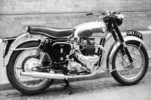
The more you ride older machines, the more you start to value a good rear brake. It seems to play a disproportionate role, not least in providing a decent hold on steep hills where some twin-leading shoe front brakes are of little use. Despite the weight transfer effects of braking making the front brake theoretically more important, in practice you really notice the benefit of a decent rear anchor.
Trouble is, the later pre-unit BSA twins and singles suffer from a spongy and unsatisfactory back brake, mostly down to the cable operation. In using up parts, the factory created a cross-shaft arrangement to allow the brake plate to be on the right side of the machine. But the cross shaft was run through the swinging arm spindle, thus ruling out any simple rod linkage. The snag is down to plain old geometry. The best place for the brake rod clevis is at the swinging arm centre, so that the brake rod effective length stays constant as the suspension moves. This means the brake doesn’t come on or slacken as you ride the bumps. Look at any normal brake rod and you’ll see it’s arranged this way. Having the BSA cross shaft where it is means you can’t achieve that happy situation.
There’s chat on the web about horseshoe-shaped operating levers (an old gear lever has the correct spline for the cross shaft) bent over behind the oil tank to a clevis point, but that has poor geometry and there’s a lot of springiness in the horseshoe piece. Achieving a satisfactory rod operation seemed a hard problem to solve.
You could try hydraulics, but that’s getting complicated. But the light came on when I tripped over some early model BSA A65s at last year’s international rally. The factory was obviously still using up the remaining supply of RH-side brake plates, but with rod operation achieved by a neat little relay lever. At first I thought the relay was just to get a straight-pull routing for the rod. But once I did the sums, what should have been blindingly obvious suddenly became so. If the relay clevis sits on (or even near) a line between the cam lever trunnion and swinging arm pivot, the effect on the brake by suspension movement is around 10 times less than if the rod went straight to a clevis on the operating lever. The geometry is that stark – and some careful measurements on the factory setup confirmed the alignment was spot-on.
So there was the solution. A quick search turned up a factory A65 operating lever that fitted in place of the cable one, and a couple of days of milling, drilling and fiddling turned out a relay lever and a couple of stainless rods. I was determined to get a completely straight pull without any springy Z-bend rods. The frame pillion loop positioning on the pre-unit frame is such that I had to make up a saddle arrangement to pass the loop in a straight line. I also had to space out the cam lever using a welded-in boss, just to get the geometry right. The proof of the pudding was no measurable brake action as the suspension was tested over full travel. Out on the road, the brake feel and effectiveness was transformed. ![]()


